Custom Roll Handling Equipment for Machine Loading: A 300 kg Case Study
How SINOLIFT designed a core-gripping roll lifter for controlled lifting, rotation and machine-side alignment.
Moving a large industrial roll is only half the job. At a production line, the difficult part often begins when the operator reaches the machine: the roll must be held securely, brought to the correct shaft height, turned into the required orientation and positioned accurately without marking the material. This case looks at a customer requirement that led SINOLIFT to specify custom roll handling equipment instead of recommending a standard pallet stacker. The result was a semi-electric roll lifter design built around the roll core and the way the customer intended to load and position the material.
The customer challenge: getting the roll ready for the machine
An industrial customer needed to transfer heavy cylindrical material through a production area and prepare it for accurate placement at a working position. The application involved core-based handling, controlled lifting and a change in roll orientation. The customer's industry and identity are not disclosed, so the most useful way to understand the case is through the handling requirements rather than an invented factory story. What matters is the sequence: approach the roll, secure its center, raise it, turn it and line it up with the next station. Each of those operations affects which machine a buyer should specify.
A forklift can move a pallet, and a conventional stacker can raise a load supported from below. Neither automatically solves the problem of engaging a hollow roll core or turning a suspended roll through 90 degrees. An outside clamp may be appropriate for some materials, but a sensitive film, paper or foil surface may be less tolerant of direct gripping pressure. The customer therefore needed a purpose-built handling device rather than simply more lifting capacity.
Why the loading point mattered more than the headline capacity
For this enquiry, the nominal load was 300 kg, but capacity alone did not describe a workable solution. A buyer also had to consider whether the support legs could approach the pickup point, whether the mast could reach the receiving height, how the roll would be secured during rotation and how the final few millimetres of alignment would be achieved. If the truck is too wide, the nominal capacity is irrelevant. If the mandrel does not fit the actual core, the lifting system cannot do its job. And if the operator must repeatedly push the entire truck sideways to find the machine spindle, accurate placement becomes unnecessarily difficult.
The requested geometry reflected those practical constraints. The design brief called for handling rolls up to 1,500 mm in diameter during vertical pickup and reaching a shaft-centre height of at least 1,900 mm. A tall mast and wide support-leg layout were part of the solution, but they had to be considered together with the route between the storage area and the machine.
The selected SINOLIFT solution
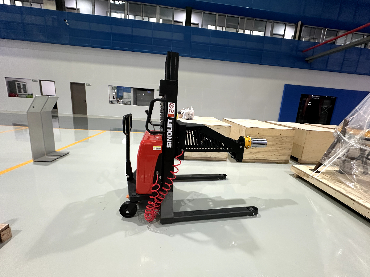
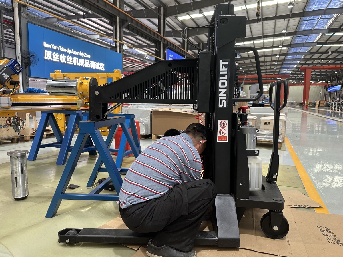
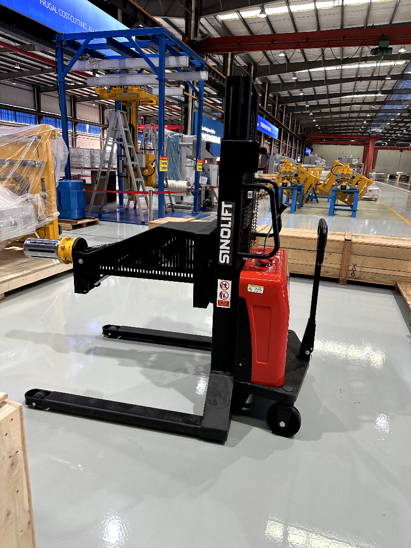
SINOLIFT configured the CTD1025AF as a custom semi-electric roll lifter with a pneumatic expanding mandrel. The operator manually guides the truck, while electric lifting, powered 90-degree shaft rotation and powered lateral adjustment assist with the functions that call for repeatable control. The mandrel expands pneumatically inside the roll core, so the load is supported through its centre instead of relying on a pair of ordinary pallet forks. This makes the machine a specialised roll-handling solution, not a general-purpose forklift.
PROJECT CONFIGURATION / CTD1025AF
|
Rated load target |
300 kg |
|
Mandrel design |
116 mm nominal structure; 3 expanding strips; 400 mm working length |
|
Roll size / lifting target |
Up to 1,500 mm roll diameter for vertical pickup; shaft centre at least 1,900 mm |
|
Powered handling |
Electric lifting; powered 90° upward rotation; 50 mm side shift each direction |
|
Travel and battery |
Manual travel; 12 V / 85 Ah maintenance-free lead-acid battery |
The reference drawing describes a 116 mm mandrel structure with three expanding strips and a 400 mm working length. Those figures identify the supplied design concept; they do not mean that every roll with a nominally similar core will fit. Core inner diameter, tolerance, material strength and the expansion range must be checked against a real sample or approved drawing. The battery listed for this configuration is a 12 V / 85 Ah maintenance-free lead-acid unit. Final equipment details remain subject to customer confirmation.
How the intended loading sequence works
The advantage of combining these functions is easiest to understand at the loading point. The following describes the intended operating sequence that the design supports, not an undocumented account of a completed production trial:
1. Approach and position. The operator brings the manually propelled lifter to the roll and checks that its legs, mast and gripping head can approach the core without contacting nearby pallets or machine guards.
2. Engage the core. The mandrel is aligned with and inserted into the roll's hollow centre. Actual insertion depth and core compatibility must be confirmed for the material being handled.
3. Grip from the inside. Pneumatic expansion activates the three-strip gripping arrangement. The handling procedure must confirm adequate engagement and holding force before lifting begins.
4. Lift and turn. Powered lifting raises the roll toward the required shaft-centre height. Powered rotation then provides the specified 90-degree change of orientation, subject to the machine's approved operating limits.
5. Make the final alignment. The powered side-shift function provides 50 mm of movement to either side, allowing small lateral corrections without constantly repositioning the entire chassis.
6. Complete the transfer. Once the roll is in the agreed receiving position, it can be transferred using the customer-approved loading procedure. Transfer method, personnel clearance and release sequence must be confirmed during commissioning.
Why an expanding mandrel was the right attachment
The expanding mandrel is the defining feature of this custom roll lifter. It enters the roll core and expands outward to establish internal contact. That arrangement helps preserve access to the roll's outer surface and may reduce contact marks compared with an external clamp, particularly for materials where the surface finish matters. It also creates a direct relationship between the attachment and the roll geometry: the buyer cannot select the lifting truck independently of the core dimensions.
An expanding mandrel is not a universal answer. A damaged core, unsuitable wall thickness, inconsistent inner diameter or inadequate air pressure can affect grip reliability. Core strength and friction conditions should be reviewed under the intended load. For another customer, SINOLIFT could need to change the mandrel diameter, working length, expansion travel, contact surface or gripping arrangement. The correct specification comes from the roll sample and handling task, not from copying the previous customer's drawing.
Three purchasing checks that prevent an expensive mismatch
Before issuing a purchase order for custom roll handling equipment, buyers should concentrate on the interfaces that are hardest to correct after manufacture.
Roll and core data. Supply maximum roll weight, diameter, width, core inner diameter, core material and any tendency toward deformation or telescoping. Clarify whether the roll arrives upright, lying on its side or mounted on a pallet. The 1,500 mm diameter allowance in this project concerns the stated vertical-pickup requirement, not every possible operating position.
Machine and access dimensions. Provide the receiving-shaft centre height, loading direction, available approach space, aisle width, floor layout and obstacles. The CTD1025AF reference layout lists an overall length of 1,580 mm, an inner leg width of 850 mm and an outer leg width of 1,050 mm. Those dimensions matter just as much as the rated load when checking access.
Power, utilities and operating procedure. Confirm the charging arrangement, compressed-air connection or supply requirements, control locations, rotation direction, expected duty cycle and required safety interlocks. Do not assume that a pneumatic expanding mandrel includes an onboard compressor. Ask which functions are included and which must be supplied by the site.
Why semi-electric operation can be a sensible choice
A fully powered vehicle is not always necessary for a short, level route between nearby workstations. In this project, manual travel was paired with powered functions where accuracy or physical effort was a greater concern. The arrangement can be useful when the lift needs to move slowly around existing equipment, then raise, rotate and fine-position a roll at the machine. It does not eliminate manual pushing, so buyers must still assess travel distance, gradients, floor condition and pushing force. For longer routes or frequent movement under load, an electrically driven alternative may be more suitable.
What buyers should verify before accepting the equipment
For a customised machine, a drawing should be treated as the start of approval rather than the final proof of performance. A sensible acceptance plan should confirm dimensions, approach clearance and mandrel-to-core fit, then demonstrate lift and lower functions, pneumatic engagement and release, 90-degree rotation, side-shift travel and stable handling with an agreed test roll. The method should also define load limits, operating instructions, emergency provisions and the process for transferring the roll to the receiving equipment. For this project, the disclosed information establishes design requirements; it does not provide independently measured cycle-time savings, reject-rate reductions or completed customer-site test results. Those outcomes should only be published when documented.
What this case means for printing, packaging and converting buyers
The same purchasing question appears in many roll-fed industries: can the equipment bridge the gap between how the material is stored and how the next machine receives it? Paper, film, flexible packaging, foil, nonwoven, textile and battery-material production can all present core-gripping or alignment requirements, although the exact attachment varies by material. A buyer should not assume that a lifter for one production line will automatically suit another. The essential lesson from this CTD1025AF case is to specify the complete loading operation, including the roll orientation and machine interface, rather than asking suppliers for a generic 300 kg lifting truck.
SINOLIFT customisation: built around the work, not a catalogue number
SINOLIFT develops custom material handling solutions for applications where standard equipment cannot meet the required load shape, handling direction or access space. This CTD1025AF project illustrates that approach: the customer required internal roll gripping, a high working position, powered orientation control and precise lateral alignment in one compact handling system. The design combined a pneumatic expanding mandrel, electric lift, 90-degree rotation and powered side shift around those requirements.
If your facility needs to load paper or film rolls onto a production machine, rotate a sensitive material roll, reach an unusually high spindle or work within restricted aisle space, share your roll dimensions, core details, load weight, machine drawing and a short video of the current process. SINOLIFT can review the operating conditions and discuss a custom roll lifter, an alternative gripping head or a different drive configuration. The right machine begins with your actual workflow, and that is where SINOLIFT's custom engineering support adds value.

Custom Rotating Clamp Stacker for Speaker Cabinets: A SINOLIFT Design Case Study
Custom Carcass Handling Equipment: SINOLIFT ML150 Case Study
Related Article