Custom Rotating Clamp Stacker for Speaker Cabinets: A SINOLIFT Design Case Study
Handling a speaker cabinet involves more than moving a heavy object from one place to another. Its size, external finish, internal components, and required working orientation all influence how it should be supported. For a production operation that needs to lift and turn cabinets, the handling equipment must address both the weight of the load and the way operators need to access it. This SINOLIFT custom rotating clamp stacker project brings those requirements together in a mobile machine designed around a specific speaker cabinet handling application.
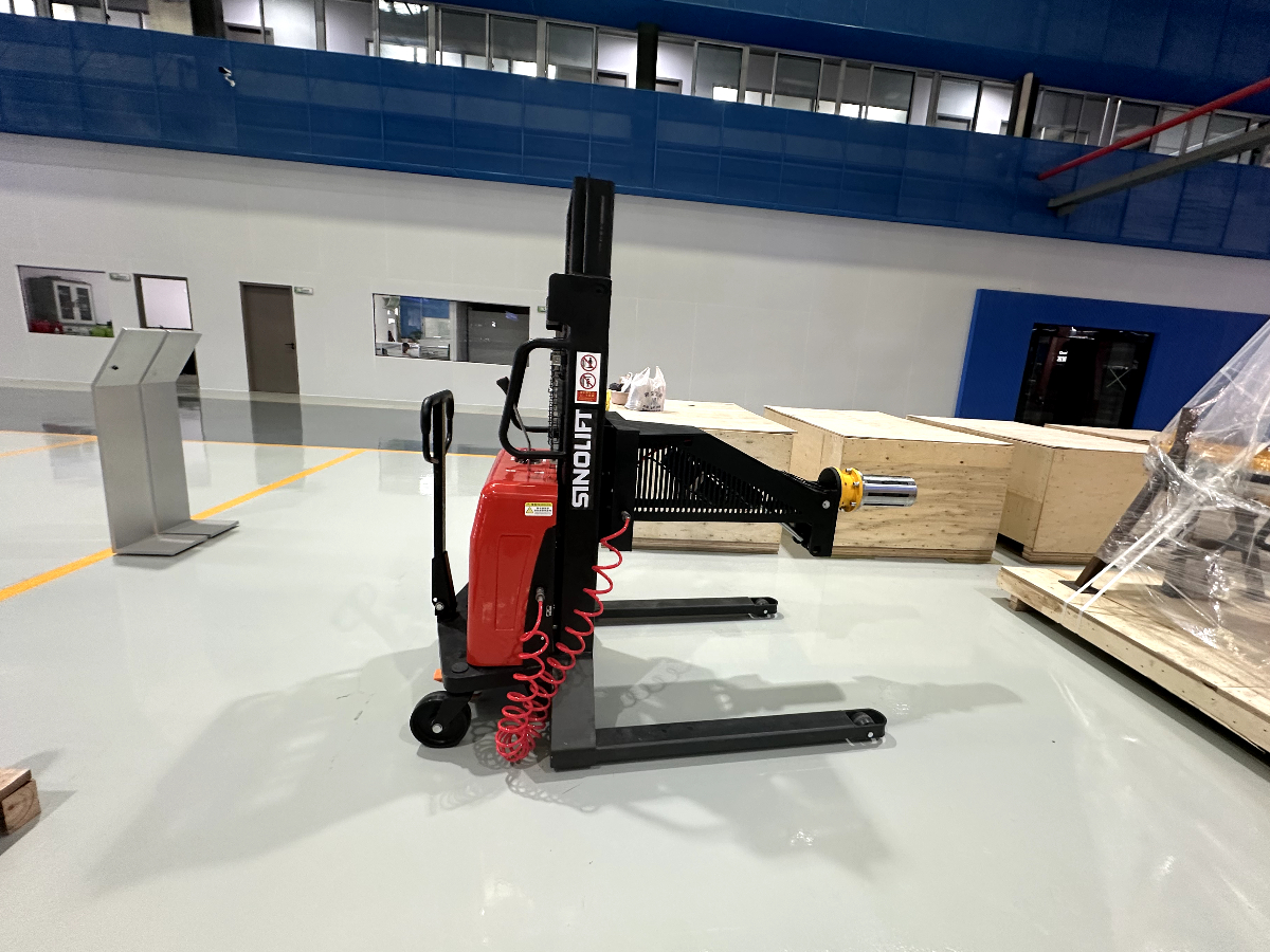
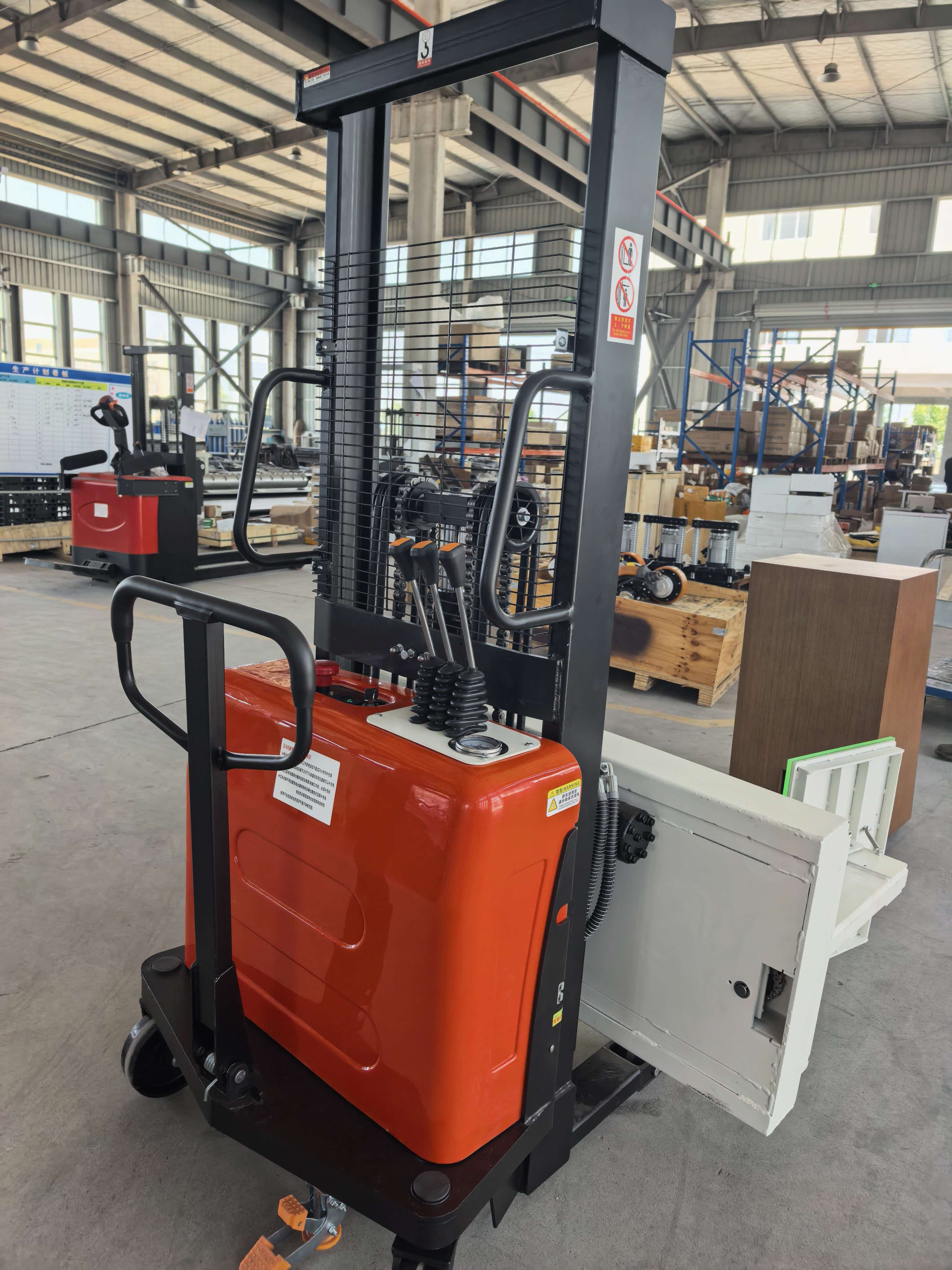
The project drawing specifies a 100 kg rated capacity, an adjustable clamp opening of 400–650 mm, powered lifting, powered clamping, and powered rotation through 360 degrees. Travel is manual: the operator pushes or pulls the truck between positions. This combination makes the product a semi-electric rotating clamp stacker, with electrical power supporting the load-handling functions while the operator controls movement across the floor. The case illustrates how a defined handling requirement can guide the configuration of the chassis, mast, gripping attachment, and rotation mechanism.
The central requirement was to grip the speaker cabinet around its middle and raise it until the bottom of the cabinet was at least 1,100 mm above the floor. That is a more useful specification for this application than a lifting height stated without reference to the load. It connects the machine’s movement to the actual cabinet and the space available beneath it. The drawing also calls for rotation in either direction, allowing the load’s orientation to be changed while it remains held by the clamp.
These requirements explain why a conventional transport trolley would address only part of the task. A trolley can support a cabinet during transfer, but changing its orientation normally requires another handling method. A platform lifter adds vertical movement, yet it does not inherently provide the side grip and rotation needed here. SINOLIFT’s design combines these functions around one load interface. The intended benefit is to reduce separate handling steps and make cabinet positioning more manageable at the point of work, subject to validation with the actual product and operating conditions.
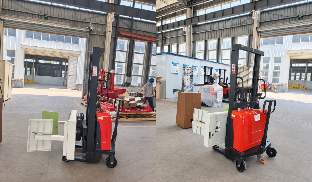
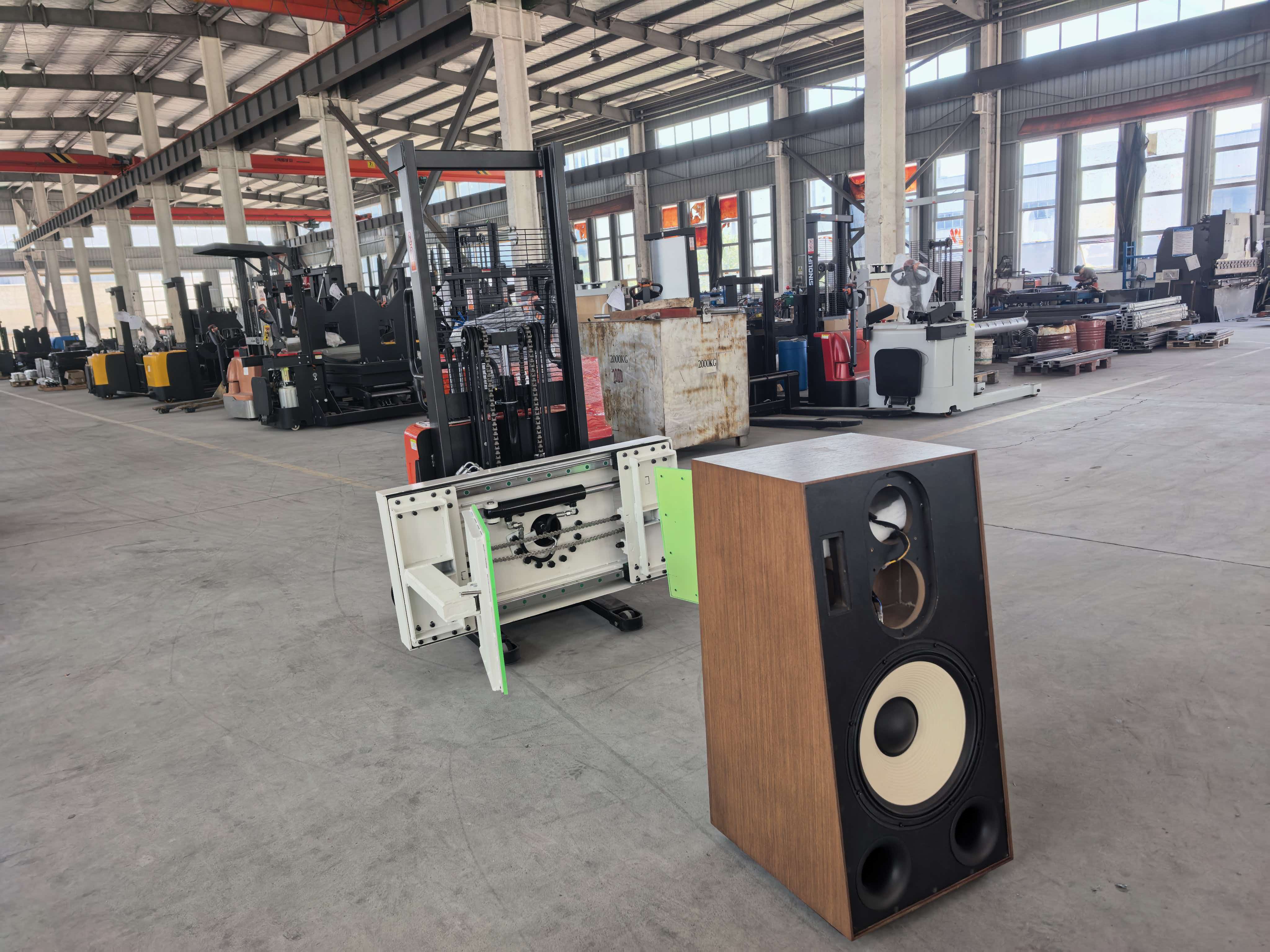
At the front of the machine, opposing flat clamp plates provide the interface with the cabinet. The drawing describes a self-adapting flat-plate clamping arrangement, with the arms opening across a specified range of 400–650 mm. This gives the project a clear dimensional envelope for the load at the gripping position. It also places attention on the surfaces that the plates contact. Cabinet handles, projecting fittings, grilles, and changes in profile must be considered when establishing a suitable grip, rather than treating overall cabinet width as the only selection criterion.
For speaker cabinet handling, the relationship between grip and surface condition deserves particular attention. A cabinet may have a painted, coated, or textured exterior, and its side panels may differ in stiffness from its internal structure. The contact area and clamping force therefore need to suit the actual cabinet construction. The supplied drawing does not identify a particular pad material or an automatic force-limiting system. Those details belong in the engineering review for the application, where the aim is to establish adequate retention without making unsupported assumptions about surface protection.
Powered rotation is another defining feature of the custom rotating clamp stacker. The drawing identifies a hydraulic motor at the rotation mechanism and specifies 360-degree rotation to the left or right. For a cabinet that needs to be presented in different orientations, this creates a handling option beyond lifting and lowering alone. Depending on the production process, that capability could support access for assembly, inspection, or positioning before a subsequent operation. These are potential uses of the configuration; the appropriate sequence should be established around the customer’s actual workstation and cabinet design.
The available rotation range must also be considered together with clearance. A rectangular cabinet sweeps a larger envelope as its corners move around the rotation axis. Cabinet height, width, depth, and the selected gripping position all affect the space required. This is why the specified clearance beneath the cabinet matters, and why the maximum cabinet dimensions need to be reviewed alongside the 100 kg capacity. A load that is within the rated weight does not automatically have a suitable shape or center of gravity for every position in the rotation cycle.
The chassis uses a counterweighted layout with short support legs, as specified in the technical requirements. This arrangement is relevant to approaching a load while leaving space around the front handling area. Its suitability depends on the relationship between the cabinet, the pickup location, and nearby equipment. The drawing indicates a width of 820 mm and a single-stage mast height of approximately 2,040 mm. These dimensions provide starting points for reviewing access routes and workstation fit, although final manufacturing dimensions must be checked against the approved engineering model.
Manual travel and powered handling are deliberately distinct in this configuration. The operator supplies the effort needed to move the truck, while the machine provides powered lifting, clamping, and turning. This is useful information for buyers comparing handling solutions because the word electric can otherwise leave the travel function unclear. For this project, the accurate description is manual push travel with powered load handling. The choice should be assessed against floor condition, travel distance, operating frequency, and the total moving mass, rather than assuming that every application requires the same drive arrangement.
The specified power source is a 12 V, 85 Ah maintenance-free lead-acid battery. It supports the machine’s powered functions within the proposed configuration. Battery capacity alone does not establish operating time: the number of lifts, rotation frequency, load weight, and operating pattern all influence energy use. For purchasing and production planning, those factors should be discussed against the expected duty cycle. The maintenance-free description applies to the battery type; the complete truck still requires the inspections and servicing appropriate to its lifting, gripping, hydraulic, and mechanical systems.
A practical application review begins with the cabinet itself. The engineering team needs its dimensions, maximum weight, center of gravity, intended gripping surfaces, and required starting and finishing orientations. The next step is to understand the surrounding process: where the cabinet is collected, how it is supported before pickup, the working height required, and where it is placed afterward. For this project, the 400–650 mm opening and the minimum 1,100 mm clearance beneath the raised cabinet turn part of that information into measurable design requirements.
The resulting configuration brings three powered handling functions onto a mobile chassis: lift the cabinet, hold it between the clamp plates, and change its orientation. That integration is the main value of the design. It offers a basis for reducing manual repositioning and improving access to the product during suitable operations. Actual productivity gains, staffing requirements, and surface-handling performance need to be established through application trials. This design case study therefore focuses on the documented configuration and its intended purpose, rather than presenting unmeasured improvements as completed project results.
The same engineering approach can guide discussions about other box-shaped or irregular loads. A different product may need a different contact profile, opening range, load capacity, lifting arrangement, or rotation requirement. The speaker cabinet configuration should not be assumed to suit those loads unchanged. Its wider significance is the method: define how the product must be gripped and presented, then coordinate the attachment and truck around that task. This keeps customization connected to the physical handling problem and provides a clear basis for evaluating the proposed solution.
SINOLIFT’s customization capability is demonstrated in the way this project combines a specific load rating, adjustable flat-plate clamp, powered rotation, cabinet-clearance requirement, and short-leg counterweighted chassis. Each element responds to part of the handling brief. Together, they form a purpose-built solution for a task that a general transport truck cannot fully address on its own. For manufacturers with unusual products or demanding positioning requirements, that ability to coordinate the load interface, movement, and machine layout is central to a useful custom handling solution.
If your process requires a product to be gripped, lifted, turned, and presented at a defined height, start the conversation with SINOLIFT by sharing the load drawings and the required handling sequence. Include the product’s weight, dimensions, contact restrictions, workstation layout, and desired orientation changes. SINOLIFT can use that application brief to develop a tailored proposal and identify the engineering details that need confirmation. This custom rotating clamp stacker for speaker cabinets shows the value of that approach: equipment configured around the product and the work it needs to perform, supported by SINOLIFT’s commitment to application-specific material handling.
Custom Roll Handling Equipment for Machine Loading: A 300 kg Case Study
Related Article